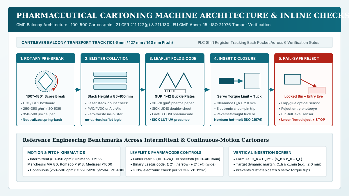
Selecting the wrong loading axis between a horizontal cartoning machine and a vertical cartoning machine causes high-center-of-gravity glass vials to tip and shatter at the carton mouth or collated blister stacks to flutter and jam during insertion. Rather than treating horizontal machines simply as high-speed units and vertical machines as footprint savers, pharmaceutical secondary-packaging engineering matches the loading vector to three physical and regulatory constraints: primary container center-of-gravity stability (H/D), patient leaflet insertion trajectory under US 21 CFR 211.122(g), and load-bearing flap closure orientation under 21 CFR 211.130 and 21 CFR 211.132.
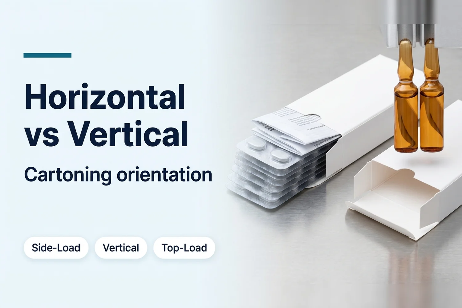
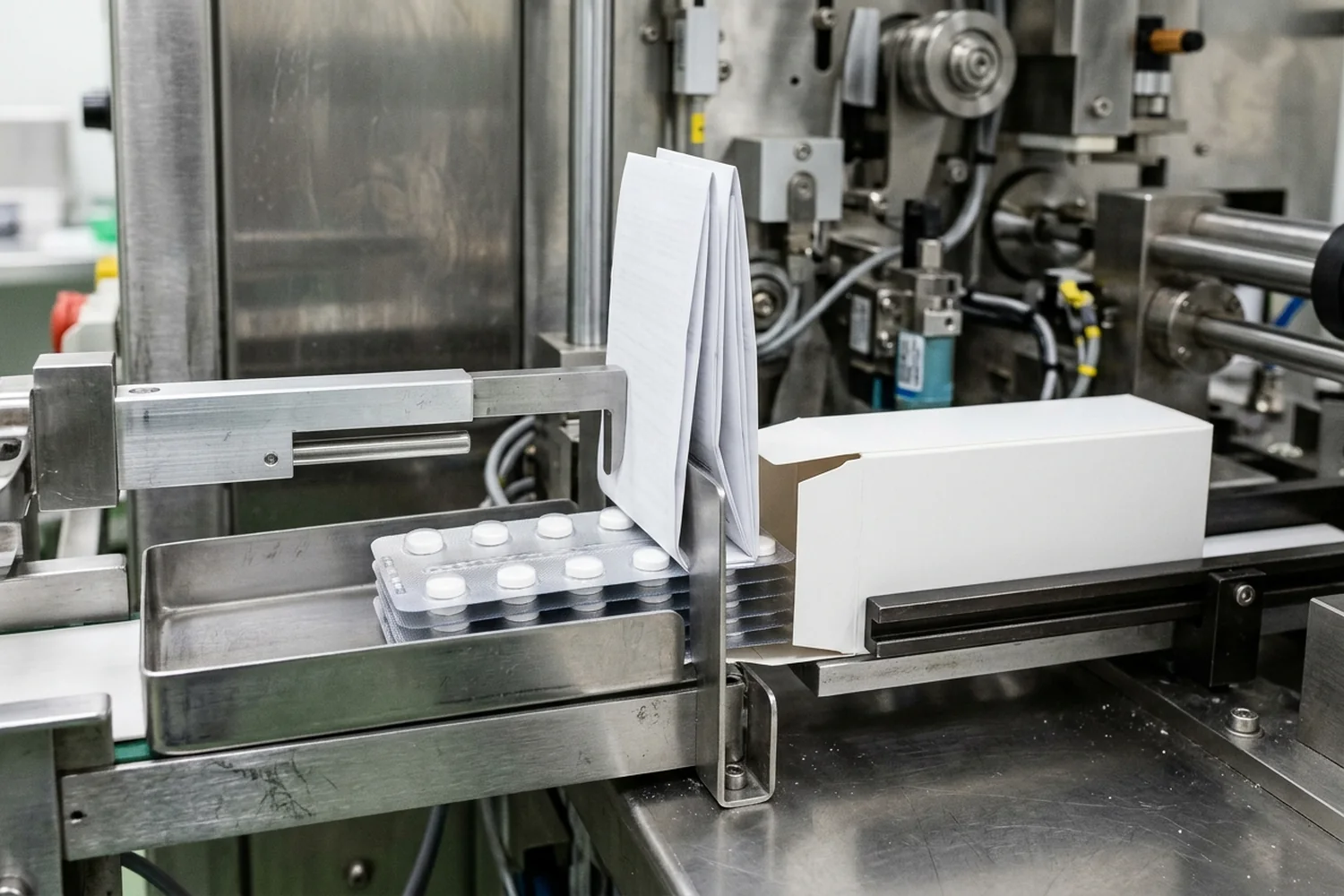
A horizontal cartoning machine erects a pre-glued tubular carton sleeve horizontally and uses a side-acting mechanical or servo pusher to slide flat blister stacks (blister cartoning machine duty), pouches, or horizontally laid rigid containers into the open carton while sweeping an inline folded leaflet into a U-wrap. A vertical cartoning machine erects the tubular sleeve upright, tucks or glues the bottom flaps first, and lowers upright bottles or twin vials downward along the gravity axis. A top-load cartoning machine forms an open-top tray or carton from a flat die-cut blank around a solid uncut bottom panel and loads multi-vial partitions, syringes, or sachets from above via pick-and-place tooling. While the parent pharmaceutical cartoning process guide outlines the overall six-step secondary-packaging workflow, this guide defines the mechanical selection boundaries, container tipping screening math, and URS qualification checks that govern machine orientation.
Horizontal, vertical, and top-load cartoning machine architectures compared
Before comparing cam or servo motion profiles, packaging engineers must separate the three primary loading geometries—horizontal side-load, vertical end-load, and top-load—by how the paperboard blank is erected, which carton aperture receives the product, and which panel carries the container weight during transport.
| Engineering Dimension | Horizontal Cartoning Machine (Side-Load) | Vertical Cartoning Machine (Upright End-Load) | Top-Load Cartoning Machine (Mandrel / Dead-Plate Tray) |
|---|---|---|---|
| Representative OEM Platforms | Uhlmann C 130, C 2155, C 200 (intermittent, 120–200 cpm), C 2156 / C 2206 (150–200 cpm), C 2305 / C 2504 (continuous, 300–500 cpm); Romaco Promatic P 91 L / P 91 / P 91S (70–120 cpm) & PC 4000 (up to 450 cpm); Serpa P100 |
Serpa P120 Vertical Cartoner (upright pharmaceutical bottle, twin-vial, and thick-insert configurations) |
INVpack TL6 (60 ppm); Serpa Top Load Cartoner (with dual carton former and robotic pick-and-place loading) |
| Carton Blank Supply & Erection | Pre-glued flat tubular sleeve pulled from magazine via rotary or reciprocating vacuum arms; longitudinal scores pre-broken up to 160°–180° and placed horizontally between transport lugs |
Pre-glued flat tubular sleeve pulled from magazine, erected into an upright vertical shaft, and indexed in vertical transport lugs or belts | Flat, unglued die-cut blank erected vertically downward through a forming die or around a mandrel to create an open-top tray with a solid uncut bottom panel |
| Product Loading Vector | Horizontal side push (X/Y plane): Mechanical or servo pusher slides product laterally from a synchronized bucket chain through the side end opening |
Vertical top-down insertion (Z axis): Starwheel, timing screw, vertical gripper, or hand-load lane lowers upright containers downward through the top end opening |
Vertical pick-and-place (Z axis): Delta/multi-axis robotics or overhead gantries place single or grouped packs downward into the widest cross-sectional top aperture |
OEM Carton Size Envelope (A × B × C or L × W × H) |
Uhlmann C 130: up to 100 × 85 × 150 mm; C 2155: up to 115 × 100 × 170 mm; C 2305 / C 2504: up to 105 × 105 × 155 mm / 80 × 90 × 155 mm; Romaco P 91 L / P 91 / P 91S: A: 15–150 mm, B: 15–80 mm, C: 60–250 mm |
Format-matched to upright cylindrical or oval bottle/vial diameter (A × B) and overall container plus cap/dosage-cup height (C) |
INVpack TL6: Length 80–210 mm, Width 80–300 mm, Height 20–190 mm (4,400 × 2,900 × 2,000 mm machine footprint, 2,500 kg) |
| Primary Pharmaceutical Formats | Collated thermoformed or cold-formed blister stacks (blister cartoning machine standard), pillow pouches, collapsible tubes, and vials/syringes carried in horizontal bucket pockets or trays |
Upright liquid syrup and ophthalmic dropper bottles, bare single or twin glass vials, bottles with seated over-cap dosage cups, and multi-insert kits | Multi-vial parenteral kits with internal paperboard partitions/dividers, fragile glass ampoules/syringes, diagnostic test-strip kits, and high-count stick-pack or sachet multipacks |
| Leaflet & Insert Feed Mechanism | Inline buckle/knife folder places 30–70 g/m² sheet perpendicular to carton mouth; advancing product sweeps leaflet into a U-wrap around the pack’s leading face |
Sidewall plunger/sword pre-insertion, bottle neck-collar placement, or high-capacity feeder inserting pre-folded thick booklets/outserts (e.g., 1.5 in / 38.1 mm thick leaflets on Serpa P120) |
Pick-and-place vacuum head lays flat or pre-folded IFUs, booklets, or reconstituting accessories directly onto the floor or top of the open tray |
| Flap Closure Sequence | Both operator-side and drive-side ends remain open during loading, then close simultaneously via bilateral reverse-tuck, straight-tuck (airplane), or hot-melt plows | Two-stage sequential closure: Bottom flaps are tucked or hot-melt glued before the loading station to support container weight; top flaps close after loading | Three-flap hinged top hood folds down over the open tray and seals to the front and side walls via hot-melt adhesive or top tuck-in tabs |
| Dominant Mechanical Failure Mode & Prevention | Upright vial tipping or leaflet telescoping: Lay slender vials flat in contoured buckets, use a synchronized counter-pusher (Romaco P 91), or switch to vertical loading |
Bottom-flap punch-through or free-fall blister scatter: Support carton base on a continuous bottom rail, use crash-lock/glued bottoms, and restrict free-drop to rigid containers | Forming-corner tear or robotic placement collision: Match die-cut blank crease tolerances to forming mandrel clearance and verify vision-guided pick coordinates |
A frequent procurement error in secondary packaging-line selection is conflating a vertical end-load cartoner with a top-load cartoner. Although both load the product downward along the vertical (Z) axis, a vertical end-load cartoner loads through the narrow end cross-section (A × B) of a pre-glued tubular sleeve, whereas a top-load cartoner loads through the wide main panel face (L × W) of a die-cut blank before the top hood is folded shut.
Container center-of-gravity (H/D) stability, vial tipping mechanics, and blister stack confinement
The physical behavior of the primary pack during acceleration determines whether horizontal pushing or vertical lowering will run without jams or container breakage under 21 CFR 211.130.
Why blister stacks require horizontal side-load confinement
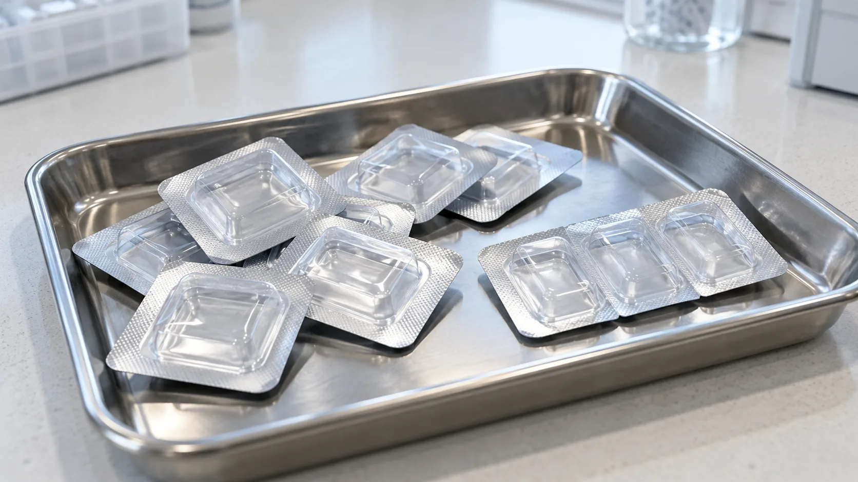
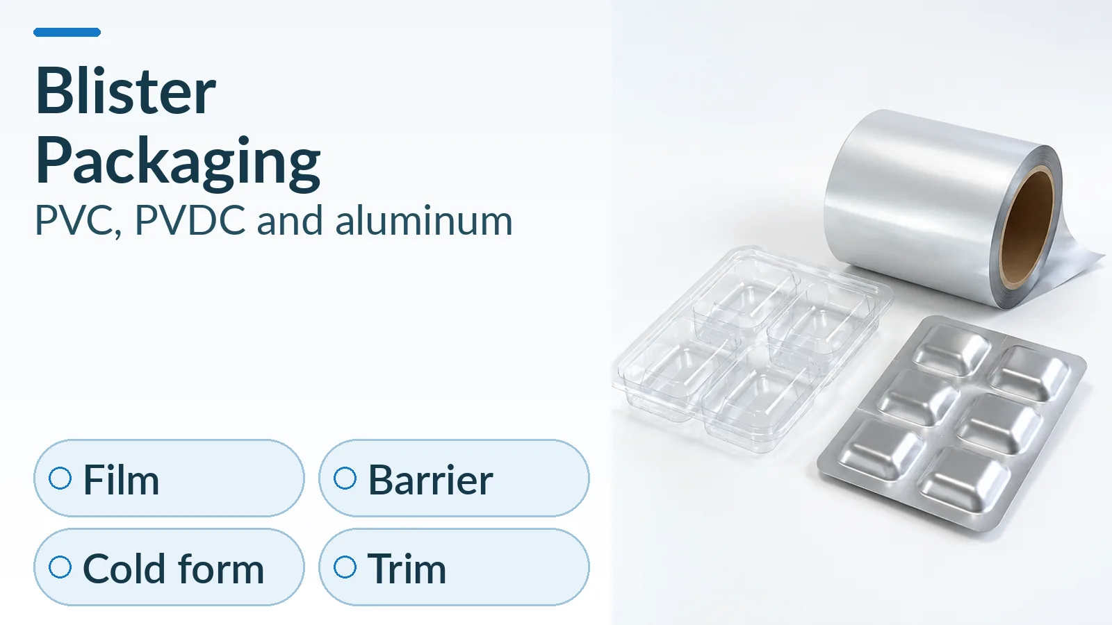
In a blister cartoning machine (such as the Uhlmann C 2155 intermittent cartoner rated up to 150 cartons/min or the continuous C 2305 / C 2504 rated at 300 to 500 cartons/min), individual thermoformed or cold-formed blister cards have a low thickness (3–10 mm) and high surface-area-to-mass ratio. Uhlmann’s blister transfer architecture keeps drop heights low as collated stacks (1 to 10 cards) enter the horizontal bucket chain. During pusher insertion, upper and lateral guide horns confine the stack so the cards cannot fan apart or rotate.
Attempting to drop a multi-card blister stack vertically down the upright shaft of a vertical cartoner removes that vertical confinement: aerodynamic drag against the flat lidding foil causes the top and bottom cards to separate, skew diagonally inside the carton walls, and jam against the upper dust flaps.
Upright cylindrical container tipping threshold under horizontal acceleration
Conversely, when packaging rigid containers—compared upstream in blister and bottle packaging—tall cylindrical glass vials, ampoules, and ophthalmic dropper bottles exhibit a high center-of-gravity height (h_cg) relative to their base contact diameter (D_base).
When an upright cylindrical container of mass m, base contact diameter D_base, and filled center-of-gravity height h_cg is pushed horizontally across a stainless deadplate (kinetic friction coefficient mu_k) at peak horizontal pusher acceleration a_p by a pusher plate contacting near h_cg without an upper retaining counter-pusher:
- Overturning moment (
tau_tip) about the leading bottom edge of the container:tau_tip = m × h_cg × (a_p + mu_k × g) - Gravitational restoring moment (
tau_rest) about the leading bottom edge:tau_rest = m × g × (D_base / 2) - Dynamic Stability Ratio (
S_R):S_R = tau_rest / tau_tip = (g × D_base) / [2 × h_cg × (a_p + mu_k × g)]
Rules-of-Thumb: If the dynamic stability ratio S_R < 1.5 (where S_R <= 1.0 represents immediate rigid-body overturning on a flat deadplate, and the 1.5 threshold provides a 50% safety margin against deadplate-to-carton lip steps), an unrestrained upright container cannot be pushed horizontally without tipping forward.
Conditional trial calculation (comparing a slender parenteral vial against a wide-base oral bottle):
- Case A — Slender
10 mLglass injection vial (trial inputs): Base contact diameterD_base = 22.0 mm(radius11.0 mm), overall heightH = 50.0 mm, filled center-of-gravity heighth_cg = 24.0 mm(H / D_base = 2.27), deadplate kinetic frictionmu_k = 0.20, gravitational accelerationg = 9.81 m/s², and intermittent horizontal pusher peak accelerationa_p = 3.50 m/s²:- Effective horizontal force ratio:
(a_p / g) + mu_k = (3.50 / 9.81) + 0.20 = 0.357 + 0.200 = 0.557. - Geometric base-to-center-of-gravity ratio:
D_base / (2 × h_cg) = 22.0 mm / (2 × 24.0 mm) = 0.458. - Stability ratio:
S_R = 0.458 / 0.557 = 0.82 < 1.0. - Engineering decision: Because
S_R = 0.82is below1.0, pushing the standing vial horizontally will tip the vial forward into the carton edge. Packaging engineering must apply one of three architectural solutions:- Vertical or top-load upright insertion: Keep the vial standing upright and load it downward along the
Zaxis on a vertical cartoning machine (such as the SerpaP120running dual-lane twin vials) or a top-load cartoning machine with internal dividers. - Horizontal bucket lay-down (
90°pitch transition): Separate incoming upright bottles via an infeed screw conveyor (as on UhlmannC 130 / C 2155 / C 200and RomacoP 91lines) and lay the container horizontally into a contoured bucket pocket before the pusher station, reducing effective center-of-gravity height to11.0 mmwhile supporting the full50.0 mmsidewall. - Counter-pusher or puck confinement: Engage an opposing pneumatic/servo counter-pusher (a standard feature on the Romaco Promatic
P 91series for unstable products) that clamps the container top/base during the horizontal stroke, or transport the upright vial inside a thermoformed tray or recirculating puck.
- Vertical or top-load upright insertion: Keep the vial standing upright and load it downward along the
- Effective horizontal force ratio:
- Case B — Wide-base
120 mLoral tablet bottle (trial inputs): Base contact diameterD_base = 52.0 mm, overall heightH = 90.0 mm, filledh_cg = 42.0 mm(H / D_base = 1.73), deadplate frictionmu_k = 0.18, and servo-profiled horizontal accelerationa_p = 1.50 m/s²:- Effective horizontal force ratio:
(1.50 / 9.81) + 0.18 = 0.153 + 0.180 = 0.333. - Geometric ratio:
52.0 mm / (2 × 42.0 mm) = 0.619. - Stability ratio:
S_R = 0.619 / 0.333 = 1.86 > 1.5. - Engineering decision: The bottle passes the tipping threshold for guided horizontal transfer, although a vertical cartoning machine remains preferred whenever an unsealed over-cap dosage cup is seated on top of the bottle closure prior to cartoning (as configured on the Serpa
P120).
- Effective horizontal force ratio:
Gross machine cycle rate vs. accepted multi-vial carton output
When sizing either a horizontal or vertical cartoner for multi-vial or multi-blister packs, keep the gross machine cycle rate (Q_gross) distinct from net accepted output (Q_accepted):
Q_gross = U_in / N_pack
Q_accepted = (U_in / N_pack) × Y_line
Where U_in is the upstream primary container feed rate (units/min), N_pack is the primary unit count per carton, and Y_line is the accepted-pack yield fraction after inline pharmacode, leaflet-presence, and checkweigher rejections. For a parenteral line feeding U_in = 180 vials/min into a twin-vial carton (N_pack = 2 vials/carton) at an accepted yield fraction Y_line = 0.985, gross carton demand is Q_gross = 180 / 2 = 90 cartons/min and accepted output is Q_accepted = 90 × 0.985 = 88.65 good cartons/min—requiring an intermittent cartoner rated at 120 to 150 cartons/min (such as the Romaco P 91S at 120 cpm or Uhlmann C 2155 / C 130 at 150 cpm) to maintain a 30%+ surge recovery margin.

Patient leaflet feed trajectory: horizontal U-wrap sweeping vs. upright booklet and top-load placement
Under 21 CFR 211.122(g), every pharmaceutical line using cut labeling and patient inserts must verify correct labeling via 100% electronic inspection or equivalent automated controls, and under 21 CFR 211.130, finished packs must be inspected to confirm leaflet presence and integrity. While the 6-gate binary Laetus pharmacode and SICK UV luminescence sensor interlock chain is detailed in pharmaceutical cartoning machine: leaflet, pharmacode and tuck checks, the mechanical path that carries the leaflet into the carton changes completely between horizontal, vertical, and top-load machines.
1. Horizontal side-load: perpendicular intercept and accompanied U-wrap
On a horizontal cartoning machine (Uhlmann C 2155 / C 2305 / C 2504, Romaco Promatic P 91), an inline stacking or reel-fed buckle/knife folder folds lightweight pharmaceutical paper (30–70 g/m²) and transfers the folded strip into mechanical retaining fingers positioned perpendicular (90°) to the open carton mouth.
As the horizontal product pusher advances the blister stack or laid-down bottle, the leading face of the primary pack intercepts the midpoint of the leaflet, bends the paper into a tight U-wrap, and slides both the pack and the wrapped leaflet into the horizontal sleeve simultaneously. The primary pack acts as a rigid internal mandrel that pulls the paper past the dust flaps without buckling. Romaco’s zero-waste logic feeds a carton blank and triggers the leaflet folder only when an upstream sensor confirms a complete product in the bucket.
2. Vertical end-load: sidewall plunger, collar placement, and thick booklet feeders
On a vertical cartoning machine, lowering a bottle downward into an upright carton cannot reliably sweep a thin flat-folded sheet (30–70 g/m²) across the carton mouth:
- If a flat sheet is laid across the top aperture and pushed down by the rounded base of a glass bottle, the paper billows outward, catches on the upper score lines or dust flaps, and either tears or cocks the bottle at an angle.
- Furthermore, US prescription and multi-language hospital packs frequently require bulky pre-folded booklets or glued outserts rather than thin single-sheet folds.
Vertical pharmaceutical cartoners solve this through three dedicated trajectories documented on platforms such as the Serpa P120 Vertical Cartoner:
- High-capacity thick booklet/insert feeder: On the Serpa
P120twin-vial configuration, a high-capacity, high-speed rotary/reciprocating insert feeder places1.5 in(38.1 mm) thick pre-folded leaflets/booklets vertically alongside dual lanes of vials inside the upright carton, with over9 ft(2.74 m) of accessible load frame for multi-insert combinations. - Sidewall sword / plunger pre-insertion: For thinner folded leaflets on vertical bottle lines, a dedicated vertical blade or vacuum plunger pushes the pre-folded leaflet down against one interior sidewall of the erected carton before the bottle descends into the adjacent space.
- Top-of-cap / dosage-cup & outsert placement: On oral liquid lines, the Serpa
P120places a plastic dosage cup over the bottle closure and positions a top insert above or beside the bottle neck before the top carton flaps are plowed shut.
3. Top-load cartoning: direct open-aperture placement
On a top-load cartoning machine (such as the INVpack TL6 or Serpa Top Load Cartoner), the carton is erected as an open-top tray whose full length-by-width (80–210 mm × 80–300 mm on the TL6) aperture faces upward. A vacuum pick-and-place arm lays a flat, Z-folded, or booklet instruction-for-use (IFU) sheet flat on the uncut bottom panel before the product array is lowered—or places the booklet directly on top of the nested vials, syringes, or sachets right before the three-flap top hood closes. Because the leaflet never crosses a narrow end-flap throat during product push, leaflet telescoping is eliminated.
| Leaflet & Insert Parameter | Horizontal Side-Load Cartoner | Vertical End-Load Cartoner | Top-Load Cartoner |
|---|---|---|---|
| Standard Insert Format | Inline buckle/knife folded sheet (30–70 g/m²), rotary pre-folded booklet, or accompanied tray card |
Pre-folded thick booklet/outsert (up to 1.5 in / 38.1 mm on Serpa P120), sidewall-inserted fold, or over-cap dosage cup + insert |
Flat sheet, pre-folded booklet, package divider card, or multi-component kit IFU |
| Insertion Mechanics | Product pusher sweeps perpendicular leaflet into a U-wrap around the leading pack face | Dedicated insert feeder / vertical plunger places booklet beside upright vial/bottle or on top of closure | Vertical pick-and-place vacuum head drops leaflet flat onto tray floor or atop loaded product array |
| Primary Jam / Defect Risk | Leaflet telescoping: Sheet lags behind blister stack and crumples at carton mouth if vertical clearance C_h is too tight |
Flap snagging or booklet wedging: Free-falling sheet catches upper dust flap, or thick booklet tilts upright vial if compartment divider is absent | Air-cushion float: Unfolded lightweight sheet shifts under air turbulence before top hood closes unless held by vacuum or product weight |
| 21 CFR 211.122(g) Verification Point | Dual-side pharmacode scan at folder exit + UV luminescence / photoeye check in transfer fingers prior to pusher stroke | Barcode/vision scan on high-capacity insert feeder + vertical presence photoeye verifying booklet depth inside upright pocket | Vision/barcode verification at pick-and-place magazine + overhead camera verification inside open tray prior to hood folding |
Carton score orientation, bottom-flap load bearing, and tuck-in vs. hot-melt closure (21 CFR 211.132)
Die-cut folding cartons converted from virgin-fiber paperboard (with cutting-press caliper limits reaching 0.81 mm / 0.032 in for heavy folding boxboard and micro-flute grades) experience fundamentally different structural loads depending on whether the carton travels horizontally or vertically through the closing station.
1. Bilateral horizontal end closure (RTE, STE/airplane, fifth-panel, and hot-melt)
On a horizontal cartoning machine (Uhlmann C 2155 / C 2305, Romaco Promatic P 91), the carton sleeve rests horizontally on its lower main panel while carried between transport chains. The weight of the blister stack or horizontal vial tray is supported continuously by the lower carton panel and guide bed—never by the end flaps during machine transport.
Because both the operator-side and drive-side ends of the horizontal sleeve are open and unloaded, stationary and rotary plows close both ends simultaneously in a single pass. Uhlmann and Romaco horizontal cartoners support six interchangeable closure styles:
- Reverse-tuck end (RTE): Top and bottom tuck panels hinge from opposite main panels, maximizing blank nesting efficiency on the converter’s die-cutting sheet.
- Straight-tuck end (STE / airplane flaps): Both tuck flaps hinge from the same main panel so neither front-panel score edge is interrupted by a raw cut tab.
- Tuck-in with fifth panel (
5th panelon RomacoP 91) or fourth-flap reclosable (Uhlmann): Provides an extended display or reclosable cover panel. - Double-sided hot-melt closure or combination tuck-in + glue spot: Applies hot-melt adhesive across both end flaps (or combines a mechanical tuck with a tamper-evident glue spot) to create a permanent fiber-tear bond.
2. Vertical end-load bottom-flap load bearing and punch-through prevention
On a vertical cartoning machine (Serpa P120), the tubular sleeve is oriented with its longitudinal axis vertical (Z axis). Consequently, the machine cannot close both ends simultaneously after loading:
- Pre-load bottom closure: Immediately after the rotary opener erects the vertical sleeve, the lower plows and tuckers (or hot-melt glue guns) must close and lock the bottom end flaps before the carton indexes under the product loading starwheel or twin-vial loader.
- Axial drop and static load support: When a filled glass bottle or twin-vial pair of total mass
mis lowered into the upright carton, the bottom flap assembly absorbs the downward deceleration impulse plus the continuous static loadF_static = m × g. - Post-load top closure: After the container and thick booklet (
1.5 inon theP120) are seated inside the sleeve and verified by height sensors, the upper plows fold the top dust flaps and tuck or glue the top main flap closed.
If a heavy glass syrup or parenteral bottle is loaded into a vertical carton equipped only with an unglued friction reverse-tuck bottom flap, the concentrated base load can deflect the dust flaps downward and pop the friction tuck tongue open (bottom-flap punch-through). Engineering specifications prevent bottom blow-out through three controls:
- Continuous stainless bottom support rail: A polished deadplate rail runs directly beneath the closed bottom panel from the bottom-tuck station through the product-loading and top-closing stations, carrying the vertical container load until the carton is discharged onto the takeaway belt.
- Crash-lock (auto-bottom) or hot-melt glued bottom flaps: For heavy glass bottles, converters supply pre-glued crash-lock bottoms or the vertical cartoner applies hot-melt adhesive to the bottom flaps so solidified adhesive shear strength—rather than friction tab stiffness alone—carries the container weight in distribution.
- Controlled vertical lowering (gripper/elevator vs. free drop): Lowering vials via servo grippers, vacuum plungers, or support elevators until the base contacts the bottom panel eliminates free-fall impact spikes.
3. Top-load solid uncut bottom panels and tamper-evident hood closure (21 CFR 211.132)
On a top-load cartoning machine (INVpack TL6, Serpa Top Load Cartoner), the flat die-cut blank is formed around a mandrel or pushed through a forming cavity so that the bottom of the carton is a continuous, uncut paperboard panel bounded by four creased sidewalls. Because there is no bottom seam or tuck flap, bottom punch-through is physically impossible—making top-load cartons well suited for heavy multi-vial kits and fragile parenteral partitions.
For over-the-counter (OTC) human drug products sold at retail in the United States, 21 CFR 211.132(b)(1) requires a tamper-evident packaging system having one or more indicators or barriers to entry that are distinctive by design and provide visible evidence to consumers if breached, accompanied by a prominent labeling statement under 21 CFR 211.132(c) that remains unaffected when the feature is opened. Across the three cartoner architectures, tamper-evident compliance is engineered by matching the closure mechanism to the loading orientation:
- Horizontal and vertical tubular cartons: Seal both end flaps with hot-melt adhesive engineered for 100% paperboard fiber tear (paired with a perforated tear-strip opening), apply tamper-evident security tape/vignette labels over friction tuck joints (such as via a downstream Serpa
TEL10 Tamper Evident Labeler), or apply full-carton film overwrap as detailed in pharmaceutical overwrapping. - Top-load tray cartons: Fold the three-flap hinged top hood over the open tray and bond the front and side hood flaps to the outer sidewalls using hot-melt adhesive behind a perforated tear-away zipper strip, creating a three-sided tamper-evident barrier that cannot be reclosed once torn.
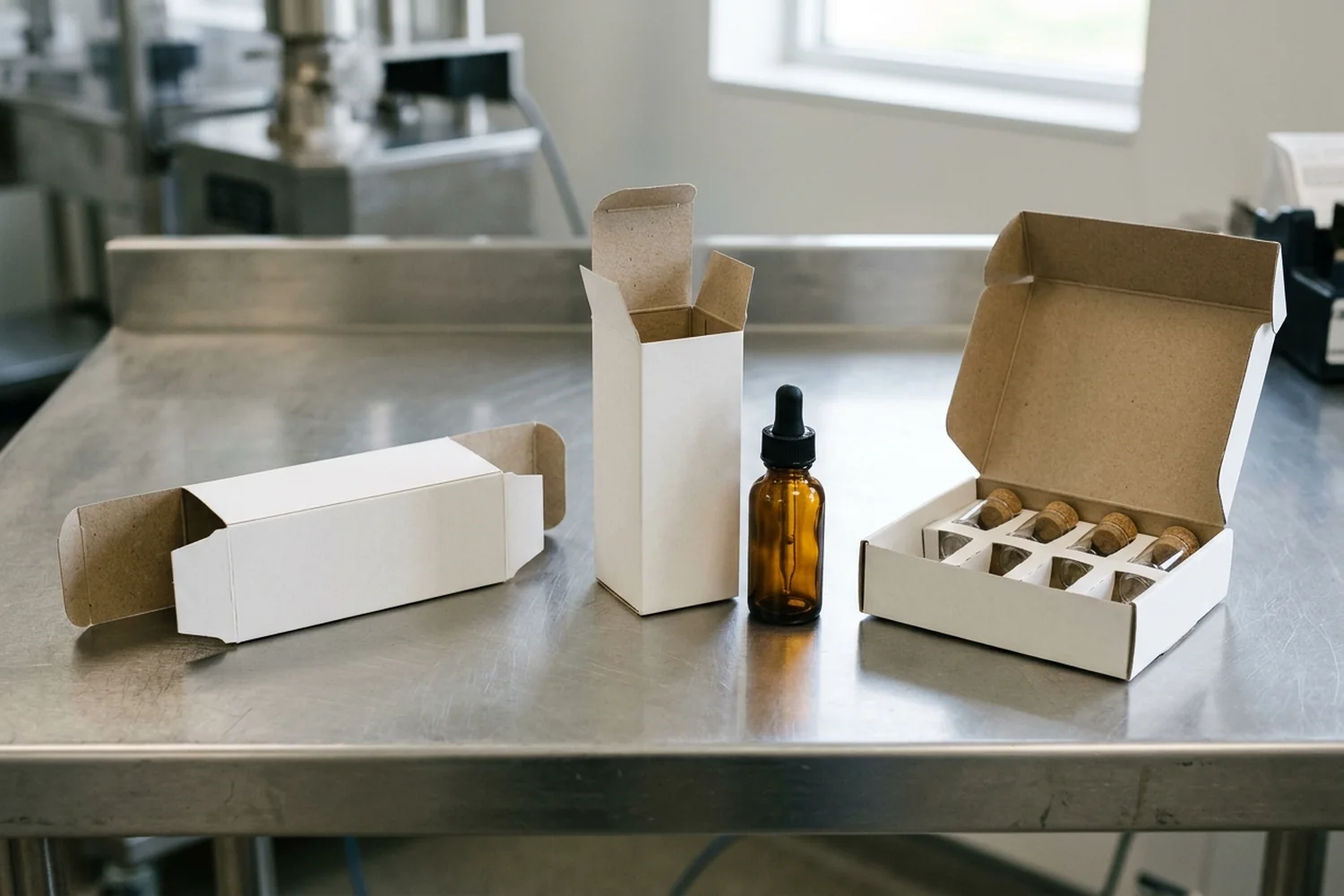
Engineering verification checklist: container center-of-gravity and loading-direction URS matrix
Under EU GMP Annex 15 (Section 3: Qualification stages for equipment, facilities, utilities, and systems) and US 21 CFR 211.130, the User Requirements Specification (URS) defines the essential operational and quality boundaries that must be verified during Factory Acceptance Testing (FAT), Site Acceptance Testing (SAT), and Operational Qualification (OQ).
Use the engineering verification matrix below (Pharmaceutical Horizontal, Vertical & Top-Load Cartoner Container Center-of-Gravity and Loading-Direction Verification Checklist) to lock down container stability, leaflet trajectory, and closure requirements before issuing an equipment URS or transferring parameters into the packaging equipment URS checklist.
| Check ID & URS Parameter | Required Engineering Input & Units | Horizontal Side-Load Boundary | Vertical End-Load Boundary | Top-Load Tray Boundary | FAT / OQ Acceptance Verification Method |
|---|---|---|---|---|---|
| URS-ori-01: Primary container geometry & mass | Container height H (mm), base contact diameter D_base (mm), gross filled mass m (g), and filled center-of-gravity height h_cg (mm) |
Flat blister stacks (1–10 cards), pouches, or rigid containers laid horizontally in contoured buckets (h_cg minimized) |
Upright cylindrical/oval bottles and single/twin vials (H / D_base > 1.8) that must remain vertical |
Multi-vial arrays, fragile parenterals in dividers, syringes, or high-count sachet/stick multipacks | Measure worst-case min/max container dimensions across 3 supplier lots and record in URS format drawings |
URS-ori-02: Dynamic tipping stability ratio (S_R) |
Peak transfer acceleration a_p (m/s²), deadplate friction mu_k (dimensionless), and S_R = (g × D_base) / [2 × h_cg × (a_p + mu_k × g)] |
Require S_R >= 1.5 for upright transfer; if S_R < 1.5, mandate 90° horizontal bucket lay-down, puck handling, or counter-pusher (Romaco P 91) |
Eliminates horizontal pusher tipping torque by lowering upright container along gravity (Z) axis via starwheel or gripper |
Eliminates horizontal tipping by lowering containers vertically into partitioned cells via pick-and-place tooling | High-speed video / 30-minute uninterrupted FAT run at 100% maximum rated speed with zero container topples |
| URS-ori-03: Upstream orientation & feed handoff | Incoming container state (upright single-file conveyor, multi-lane blister punch, or random bulk) and pitch transition | Direct blister stack transfer (Uhlmann C 2305 / C 2504) or screw conveyor separation (Uhlmann C 130 / C 2155) into horizontal buckets |
Upright single- or dual-lane conveyor into timing screw / starwheel / tray loader (Serpa P120 twin-vial feed) |
Overhead robotic pick-and-place synchronized with primary thermoformer, syringe feeder, or stick-pack lanes (INVpack TL6) |
Verify buffer drainage and zero container-to-container glass impact during upstream stop/start transitions |
| URS-ori-04: Patient leaflet / booklet geometry | Flat sheet dimensions (mm × mm), basis weight (g/m²), or pre-folded booklet thickness (mm / in) |
Inline buckle/knife fold (30–70 g/m²) swept into an accompanied U-wrap by the advancing product pusher |
Sidewall plunger pre-insertion or high-capacity thick booklet feeder (up to 1.5 in / 38.1 mm on Serpa P120) + dosage-cup placement |
Vacuum pick-and-place laying flat sheet or booklet on tray floor or atop loaded product array | Challenge 10/10 seeded missing-leaflet and mismatched-pharmacode packs per 21 CFR 211.122(g) |
| URS-ori-05: Carton blank style & score pre-break | Carton dimensions A × B × C (mm), board grade (GC1 / GC2), caliper (mm, <= 0.81 mm), and grain direction |
Pre-glued tubular sleeve; rotary longitudinal score pre-breaking up to 160°–180° (Uhlmann / Romaco) |
Pre-glued tubular sleeve erected upright; bottom dust and main flaps pre-broken and closed prior to product loading | Flat unglued die-cut blank formed around mandrel/cavity with a solid uncut bottom panel and 3-flap top hood | Run high- and low-humidity conditioned board lots (ISO 187) at rated speed with zero parallelogram bowing |
| URS-ori-06: Bottom-panel load support & closure | Static container weight m × g (N) plus vertical drop impulse at loading station |
Container weight carried by horizontal lower main panel; both end flaps unloaded during insertion | Bottom flap carries m × g; require continuous bottom support rail, crash-lock bottom, or hot-melt bottom seal |
Solid uncut bottom panel carries full vertical load without bottom seam or tuck tongue | Drop/load test with maximum-weight filled glass containers; 0 bottom-flap pop-opens across 1,000 packs |
URS-ori-07: Tamper-evident barrier (21 CFR 211.132) |
Closure method (RTE/STE friction tuck, hot-melt adhesive fiber tear, or tamper-evident vignette label) and tear-open feature | Bilateral hot-melt adhesive (100% fiber tear) or friction tuck + downstream tamper-evident corner labeling |
Pre-glued/tucked bottom + top hot-melt seal or downstream tamper-evident labeler (Serpa TEL10) |
Three-flap top hood hot-melt sealed to front and side walls with perforated tear-strip zipper | Destructive peel/opening inspection confirming visible, irreversible fiber tear or broken security seal |
URS-ori-08: Gross vs. accepted output (Q_accepted) |
Upstream rate U_in (units/min), pack count N_pack (units/carton), yield Y_line, and Q_accepted = (U_in / N_pack) × Y_line |
70–150 cpm intermittent (Romaco P 91, Uhlmann C 2155 / C 130); 200–500 cpm continuous (Uhlmann C 2206 / C 2305 / C 2504) |
Sized to upright bottle/vial filler speed (U_in / N_pack) plus 15–30% buffer recovery overcapacity |
60 ppm on INVpack TL6 (or dual-former high-speed robotic top-load configurations) |
1-hour OQ/PQ run measuring net accepted cartons/min and 100% fail-safe reject confirmation |
Once the loading axis, container stability mitigation, and flap closure style are selected using this matrix, specify the inline barcode, luminescence, and torque-overload sensors using the companion guide on pharmaceutical cartoning machine: leaflet, pharmacode and tuck checks, and integrate the complete secondary-packaging specification into the pharmaceutical packaging section.